
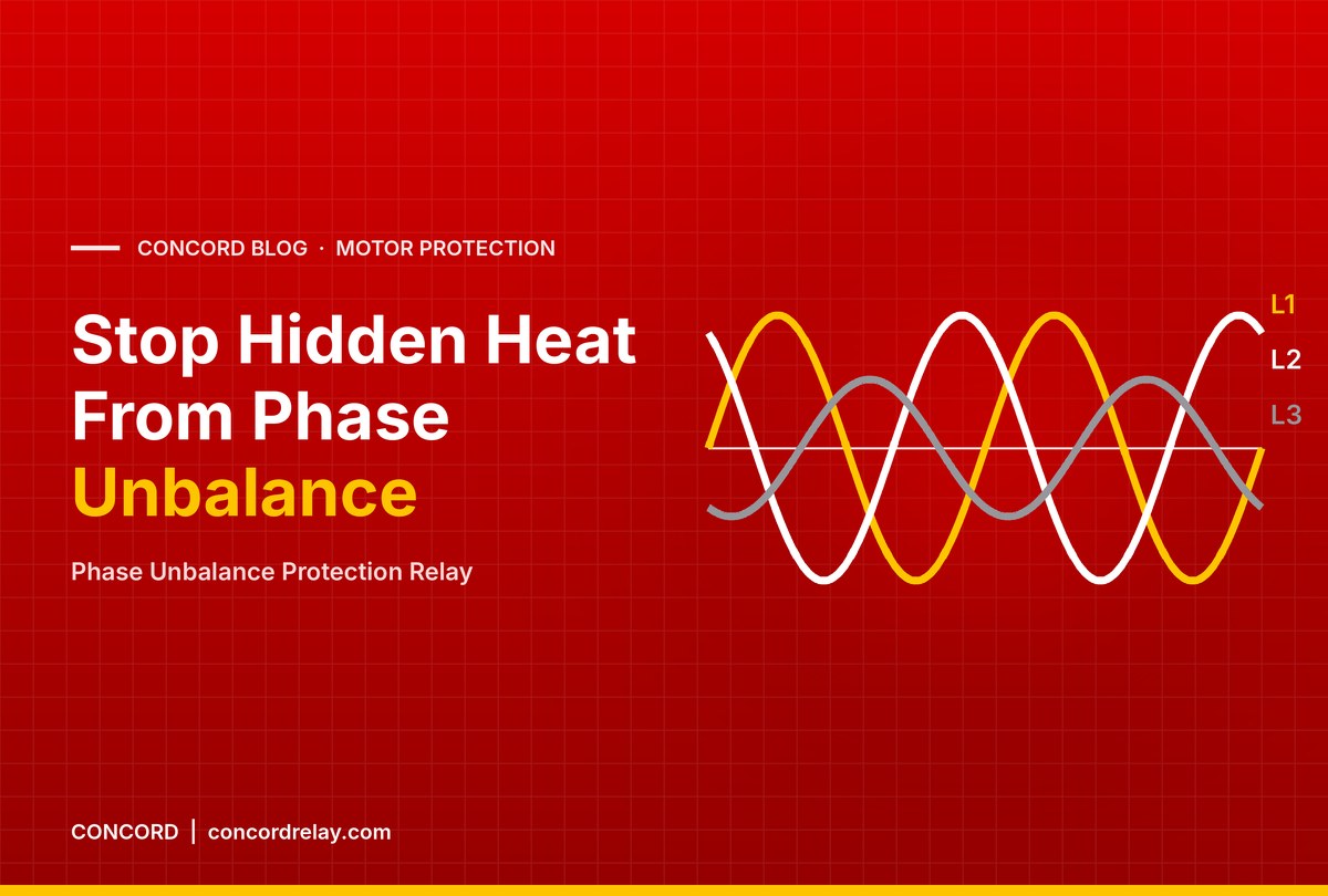
Phase Unbalance Protection Relay: Causes, Effects, Settings
A three-phase motor is designed for three equal currents displaced by 120 degrees. In real Indian plants, that ideal is rare. Unequal single-phase loads on the transformer, a loose lug, a pitted contactor tip or a long rural feeder can all leave one phase lower than the others. A phase unbalance protection relay detects when the motor’s line currents drift too far apart and stops the motor before the extra heat shortens winding life.
This guide covers the causes and effects of voltage and current unbalance, how an electronic relay detects it, and practical setting tips using CONCORD’s EOCR 3DE/3EZ.
Voltage Unbalance and Current Unbalance: What Is the Difference?
Voltage unbalance is the difference between the three supply voltages, usually expressed as the maximum deviation from the average, divided by the average, in percent. Current unbalance is the same calculation applied to the three line currents the motor draws.
The two are linked, but not one-to-one. An induction motor presents a low impedance to the negative sequence voltage created by unbalance, so a small voltage unbalance produces a much larger current unbalance. Motor standards such as NEMA MG-1 give the commonly quoted guidance that current unbalance can be several times the voltage unbalance, and that the extra temperature rise in the most loaded phase grows roughly with the square of the voltage unbalance. That is why a supply that looks only slightly uneven on a voltmeter can still overheat a motor.
Because the relay measures current, it sees the actual effect on the motor, whatever the cause.
Causes of Phase Unbalance in Motor Circuits
Supply-side causes
- Uneven distribution of single-phase loads such as lighting, air conditioners and office equipment across phases
- Long overhead lines and rural feeders with unequal phase impedance
- Faulty capacitor banks or a blown capacitor fuse on one phase
- Transformer tap or winding problems
Installation and motor-side causes
- Loose or corroded terminations, which add resistance in one phase
- Worn or pitted contactor contacts
- Unequal cable joints, especially in submersible pump cables
- Developing winding faults such as turn-to-turn shorts
- A blown fuse on one phase, which is the extreme case: phase loss or single phasing
Effects of Unbalance on a Three-Phase Motor
- Extra heating: negative sequence currents create a field rotating against the rotor, inducing high-frequency currents in the rotor and adding losses in both rotor and stator.
- Hot spot in one phase: the phase carrying the highest current overheats, even if the average current looks normal on a single ammeter.
- Reduced torque and efficiency: the opposing field reduces useful torque and raises energy consumption.
- Vibration and noise: torque pulsations stress bearings and couplings.
- Shorter insulation life: insulation ageing accelerates sharply with temperature.
A conventional overload relay set to full-load current may not trip, because the average current can stay within the set value while one phase runs much hotter. This is the gap a phase unbalance protection relay fills.
How a Phase Unbalance Protection Relay Detects the Fault

The EOCR 3DE/3EZ is an MCU based digital motor protection relay with three-phase current measurement. Its microcontroller compares the currents in L1, L2 and L3 continuously. When the difference exceeds the relay’s unbalance criterion for the set time, it trips the motor and shows phase unbalance as the trip cause on the display.
The same relay also protects against overcurrent, phase loss, reverse phase, rotor jam, locked rotor and undercurrent, with ground fault on the 3EZ using a ZCT. For large motors, external CTs extend the range up to 600A, and 3-hole combined CTs (100:5 to 400:5) are available for base mounting in the panel.
| Function | EOCR SS | EOCR SSD | EOCR DS | EOCR 3DE/3EZ |
|---|---|---|---|---|
| Phase loss (single phasing) | Yes | Yes, within 3 s | Yes, within 4 s | Yes |
| Phase unbalance | – | – | – | Yes |
| Reverse phase | – | – | Yes, within 0.1 s | Yes |
| Per-phase current display | – | Max current of any phase | – | L1, L2, L3 in sequence |
If your concern is mainly single phasing on a simple starter, our article on single phase protection relays compares the phase-loss trip times of each model.
Setting Tips for Phase Unbalance Protection
- Measure first. Before setting, run the motor at normal load and read the three phase currents on the 3DE/3EZ display. Note the natural unbalance of your supply.
- Fix the cause where possible. If one phase is consistently low, check terminations, contactor tips and cable joints before raising any setting to avoid trips.
- Set overcurrent correctly. Set the overcurrent value to the motor’s actual running full-load current so the hottest phase is also covered by overload protection.
- Allow for starting. Set the start (manoeuvre) delay, adjustable from 0-200 s, a little longer than the motor’s measured starting time, so starting transients do not cause nuisance trips.
- Treat repeated trips as a symptom. If the phase unbalance protection relay trips often on one feeder, survey the distribution of single-phase loads on that transformer.
- Record and trend. Log phase currents during routine rounds. A steadily widening gap is an early warning of a loose connection or winding problem.
- Use the TEST function. Check relay operation periodically with the front-panel TEST button and then RESET.
Remember that the relay acts on current, not voltage. It does not monitor supply voltage itself, so if supply voltage quality is a recurring problem, raise it with your electricity utility or plant electrical team as well.
Frequently Asked Questions
What causes phase unbalance in a 3-phase motor?
Uneven single-phase loading on the supply, loose or corroded terminations, worn contactor tips, unequal cable joints and developing winding faults are the most common causes.
Why is current unbalance higher than voltage unbalance?
An induction motor has low impedance to negative sequence voltage, so a small voltage unbalance drives a disproportionately large current unbalance and extra heating.
Will a normal overload relay protect against unbalance?
Not reliably. The average current can stay within the overload setting while one phase overheats. A relay with dedicated unbalance detection, such as the EOCR 3DE/3EZ, is needed.
Is phase loss the same as phase unbalance?
Phase loss, or single phasing, is the extreme form of unbalance where one phase is missing entirely. All EOCR models protect against phase loss; the 3DE/3EZ also detects partial unbalance.
Can I see phase currents on the relay?
Yes, on the EOCR 3DE/3EZ. Its display shows L1, L2 and L3 currents in sequence, and the trip cause after a fault.
For help applying phase unbalance protection to your pumps, compressors or process motors, call or WhatsApp CONCORD on +91 96670 40511 or email contact@concordrelay.com. You can also contact our team or download the EOCR brochure 2025-26.