
Types of Electronic Motor Protection Relay Explained
Product catalogues use many labels for motor relays: solid state, MCU based, digital, definite time, inverse, 3CT, ground fault. These labels describe different ways of classifying the same device, and understanding the types of electronic motor protection relay makes it far easier to compare offers and specify the right one.
This explainer groups relays by six practical criteria, shows where each design fits, and maps the CONCORD EOCR range against them. It is written for panel builders, maintenance engineers and specifiers who want to read a datasheet with confidence.
First, thermal vs electronic: the starting point
Before looking at electronic types, it helps to see what they replace. A thermal overload relay passes motor current through bimetal strips that bend as they heat up and open a contact. It is inexpensive, but its trip point shifts with ambient temperature and it offers little beyond basic overload and some phase loss sensitivity.
An electronic motor protection relay measures current with current transformers (CTs) and processes it with electronic circuits. It is ambient insensitive, allows adjustable starting delay (D-Time) and operating time (O-Time), and can detect faults that a bimetal cannot, such as locked rotor, phase reversal and undercurrent. Everything below is a sub-type of this electronic family.
Six ways to classify the types of electronic motor protection relay
1. By circuit: analog solid state vs MCU based
Analog solid-state relays use discrete electronic circuits to compare measured current with set values. They are compact, rugged and simple to set with potentiometers. The EOCR SS is an example, resistant to shock, vibration and dust.
MCU (microcontroller) based relays digitise the CT signal and process it in firmware. This allows more protection functions, precise timing (for example, reverse phase detection within 0.1 s on the EOCR DS) and features such as trip cause memory and multiple characteristics. The EOCR DS, 3DE and 3EZ are MCU based.
2. By display: LED indication vs digital display
LED types show power, run status and trip through indicator lamps; the SS and DS use two LEDs with fault diagnosis. Digital types use a 7-segment display to show actual motor current and the cause of trip. The EOCR SSD combines an analog circuit with a digital display, while the EOCR 3DE/3EZ shows all three phase currents in sequence plus a load factor bar graph.
3. By trip characteristic: definite time vs inverse time
A definite-time relay trips after a fixed O-Time once current crosses the setting, regardless of how large the overload is. It is predictable and easy to test. An inverse-time relay trips faster for larger overloads, following a thermal class curve that imitates motor heating. The SS and SSD are definite time; the DS is definite time with inverse available on request; the 3DE/3EZ offer both definite and thermal inverse (class 1-30).
4. By number of CTs: 2CT vs 3CT
A 2CT relay measures two phases and infers the third. It handles overload and phase loss well and keeps the relay compact; the EOCR SSD is a 2CT design. A 3CT relay measures all three phases directly, which supports functions such as phase unbalance and gives a true reading of each phase. The EOCR DS has 3 integral CTs, and the 3DE/3EZ display L1, L2 and L3 currents. For large motors, 2-hole combined CTs pair with the SS and 3-hole combined CTs pair with the DS, 3DE and 3EZ.
5. By CT arrangement: integral vs external
Most relays have integral CTs, with line wires passing through windows in the relay body. For small currents the wire can be looped several turns (an 05 type covers 0.1-1.2A with five turns). For large motors, an 05 type relay is used with external CTs of 5A secondary to cover running currents up to 600A, using combined CTs for EOCR or single hole SCR-CTs.
6. By ground fault capability
Standard relays work on phase currents only. Relays with a ground fault input use a zero-phase current transformer (ZCT, also called CBCT) around all phase conductors to measure leakage current. The EOCR 3EZ is the ground fault version of the 3DE and works with a CBCT/ZCT for EOCR 3EZ.
How the CONCORD range maps to these types
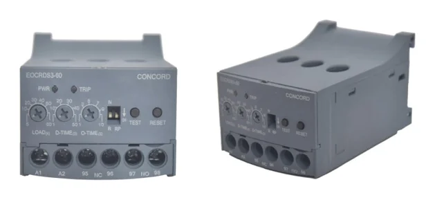
| Model | Circuit | Display | Characteristic | CTs | Ground fault |
|---|---|---|---|---|---|
| EOCR SS | Analog solid state | 2 LEDs | Definite | Integral; 2-hole external CT for large motors | No |
| EOCR SSD | Analog solid state | 7-segment digital | Definite | 2CT | No |
| EOCR DS | MCU | 2 LEDs | Definite (inverse on request) | 3 integral CTs | No |
| EOCR 3DE | MCU | Digital + bar graph | Definite / thermal inverse | 3-phase sensing | No |
| EOCR 3EZ | MCU | Digital + bar graph | Definite / thermal inverse | 3-phase sensing + ZCT | Yes |
You can compare full specifications on the CONCORD motor protection relays page.
Which type suits which job?
Knowing the types of electronic motor protection relay is useful only when it leads to a sound choice. A practical guide:
- Simple machines and OEM panels: an analog definite-time relay such as the SS gives reliable overload, phase loss and locked rotor protection in a micro-compact size.
- Single-phase or mixed motor fleets: the SSD suits 1-phase or 3-phase motors and adds current display.
- Loads sensitive to rotation: an MCU relay with reverse phase protection, such as the DS, for compressors, conveyors and some pumps.
- Critical or variable loads: a digital MCU relay with inverse characteristic, unbalance and undercurrent, such as the 3DE.
- Wet or dusty sites, submersible pumps: a ground fault type, such as the 3EZ with ZCT.
Whatever the type, remember that an electronic motor protection relay is not a short-circuit device. Short-circuit protection must come from an upstream MCCB or fuse. For a criteria-based comparison, read our guide on choosing the best motor protection relay, and for 3-phase specific faults see 3 phase motor protection relays.
Frequently Asked Questions
What are the main types of electronic motor protection relay?
They are classified by circuit (analog solid state or MCU), display (LED or digital), trip characteristic (definite or inverse), number of CTs (2CT or 3CT), CT arrangement (integral or external) and ground fault capability.
What is the difference between definite time and inverse time relays?
A definite-time relay trips after a fixed set time once current exceeds the setting. An inverse-time relay trips faster as the overload grows, following a thermal class curve.
Is an MCU based relay better than an analog relay?
MCU based relays support more functions and precise timing, such as reverse phase detection. Analog relays are simpler and compact, and are fully adequate where basic overload, phase loss and locked rotor protection is enough.
What is a ZCT in a motor protection relay?
A ZCT (zero-phase CT, also called CBCT) surrounds all phase conductors and measures leakage current to earth. It is used with ground fault relays such as the EOCR 3EZ.
Need help deciding which relay type fits your motors? Talk to CONCORD. Call or WhatsApp +91 96670 40511, email contact@concordrelay.com, or use the contact page. Download the EOCR brochure 2025-26 for detailed settings and ranges.
1 comment on “Types of Electronic Motor Protection Relay Explained”