
Definite Time Motor Protection Relay: vs Inverse Time & Settings
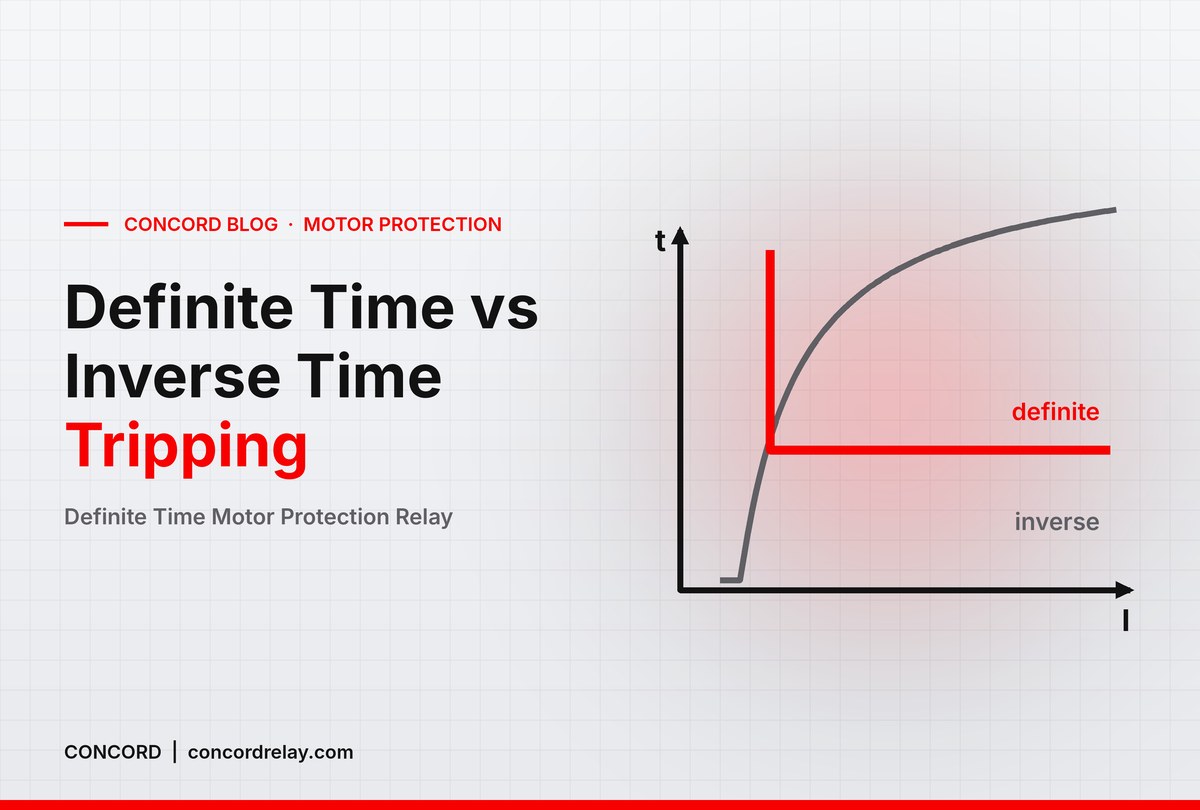
A definite time motor protection relay trips the motor after a fixed, user-set delay once current crosses the set limit, no matter how far above the limit the current has gone. That one design choice makes it predictable, easy to set and easy to check, which is why the definite-time characteristic is the default on most electronic overload relays used in Indian pump, HVAC and process panels.
The alternative is an inverse-time characteristic, where a heavy overload trips quickly and a mild overload is tolerated for longer, similar in shape to a bimetal thermal relay but with electronic accuracy. Both have their place.
This guide explains how each characteristic behaves, when to choose which, and how to set D-Time and O-Time on a definite-time relay, with worked examples you can adapt on site.
What Is a Definite Time Motor Protection Relay?
An electronic overload relay measures motor current through integral current transformers (CTs) and compares it with the set value. On a definite-time relay, the moment current exceeds the setting, an internal timer starts. If current is still above the setting when the timer runs out, the output contact changes state and the contactor drops out. If current falls back below the setting before that, the timer resets and the motor keeps running.
The trip time does not depend on the size of the overload. Whether the motor draws 110% or 180% of the set current, the relay trips after the same operating time. This gives a hard, repeatable ceiling on running current.
The two timers: D-Time and O-Time
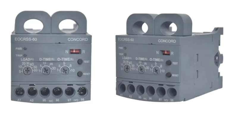
- D-Time (starting delay time): the window during starting when the motor draws high inrush current. The relay does not trip on overcurrent during this period, so the motor can reach normal running current without nuisance trips.
- O-Time (operating time): once the motor is running, the time an overcurrent is allowed to persist before the relay trips.
On the EOCR SS analog protection relay and the EOCR DS, D-Time is adjustable from 0.2 to 30 s and O-Time from 0.2 to 10 s. On the EOCR SSD, D-Time is 1 to 30 s and O-Time 1 to 10 s.
Definite Time vs Inverse Time: How They Differ
An inverse-time relay follows a curve: the higher the overload, the shorter the trip time. The curve is described by a trip class. In general terms, the class number indicates the maximum time in seconds the relay may take to trip at a defined multiple of the set current, so a lower class trips faster. This curve roughly tracks how a motor winding heats up, which lets the motor use more of its thermal capacity during short peaks.
| Aspect | Definite time | Inverse time |
|---|---|---|
| Trip time vs overload size | Fixed (set O-Time) | Shorter for bigger overloads |
| Setting effort | Simple: current, D-Time, O-Time | Current setting plus trip class |
| Short load peaks | Trips if peak lasts longer than O-Time | Tolerates mild, brief peaks |
| Best suited to | Steady loads, jam-prone machines | Cyclic or fluctuating loads |
| CONCORD models | EOCR SS, SSD, DS; 3DE/3EZ (selectable) | EOCR 3DE/3EZ (class 1-30); DS on request |
The EOCR 3DE/3EZ digital motor protection relay lets you select either definite or thermal inverse characteristics, so one model can serve both types of load.
When to Use Which Characteristic
Choose definite time when
- The load is steady once running: centrifugal pumps, fans, blowers, cooling tower motors.
- You want a firm limit on running current and the same trip time every time.
- The driven machine needs mechanical protection, as on conveyors, crushers and mixers, where a jam should stop the drive quickly regardless of current level.
- Commissioning staff need settings that are easy to understand and record.
Choose inverse time when
- The load cycles or has legitimate short peaks, for example reciprocating compressors, machine tools and some mixers.
- You want the relay curve to follow the motor’s thermal behaviour more closely.
- The protection scheme calls for a specific trip class.
For most pump and HVAC panels, a definite time motor protection relay with a well-chosen O-Time is the simpler and safer choice.
How to Set D-Time and O-Time: Worked Examples
- Current: set close to the full-load current (FLC) on the motor nameplate. A small margin for supply variation is common, but do not go beyond the motor’s rated current multiplied by its service factor.
- D-Time: measure the actual starting time (until current settles to running value) and set D-Time a few seconds longer.
- O-Time: keep it as short as the process allows without nuisance trips. Steady loads can use a few seconds; fluctuating loads need more.
| Motor (415 V, 3-phase) | Approx. FLC* | Relay range | D-Time | O-Time |
|---|---|---|---|---|
| 0.37 kW fan, DOL | ~1 A | 05 type, 3 turns looped (0.17-2 A) | 3 s | 3 s |
| 7.5 kW pump, DOL, starts in ~3 s | ~14 A | 30 type (3-30 A) | 5-6 s | 3-5 s |
| 22 kW blower, star-delta, starts in ~10 s | ~40 A | 60 type (relay in main supply line) | 13-15 s | 5 s |
| 75 kW motor | ~130 A | 05 type + 200:5 external CT (setting ~3.25 A secondary) | As per start time | 5 s |
*Indicative values only; always use the nameplate FLC.
Notes on the examples
- Small motors: looping the line wire through the internal CT more than once improves resolution on small currents. On the 05 type, three turns give a 0.17-2 A range.
- Star-delta starters: D-Time must cover the star period and the changeover current peak.
- Large motors: with 5 A secondary external CTs, an 05 type relay protects motors up to 600 A. CONCORD’s combined CTs for EOCR come in 100:5 to 400:5 ratios.
For a full walk-through of ranges, contacts and control voltages, see our guide to overload protection relay specifications.
Testing, Locked Rotor and Other Functions
Definite-time overcurrent is only one function. Each model handles other faults with its own timing:
- EOCR SS: over current and phase loss operate within O-Time; locked rotor within O-Time + D-Time.
- EOCR SSD: phase loss within 3 s; locked rotor trips immediately if 200% or more of set current continues after D-Time.
- EOCR DS: phase loss within 4 s, locked rotor within D-Time, phase reverse within 0.1 s.
After setting, press the front-panel TEST button. The relay trips after D-Time + O-Time without the motor being electrically loaded, confirming the timers work. Press RESET afterwards. On digital models, compare the displayed running current with your setting to confirm the margin. If you need faster responses on specific faults, read our article on the instant motor protection relay.
Remember that short-circuit protection is not the job of an overload relay. An MCCB or fuse upstream must clear short-circuit currents.
Frequently Asked Questions
What is the difference between a definite time and an inverse time overload relay?
A definite-time relay trips after the same set delay for any overload above the setting. An inverse-time relay trips faster as the overload increases, following a trip class curve.
What should O-Time be set to on a motor protection relay?
As short as the load allows without nuisance trips. Steady loads such as pumps and fans often work well with a few seconds; fluctuating loads need longer O-Time or an inverse characteristic.
Why does my overload relay trip while the motor is starting?
Usually D-Time is shorter than the actual starting time. Measure the start time and set D-Time a few seconds longer, especially on star-delta starters and high-inertia loads.
Can one relay offer both definite and inverse time characteristics?
Yes. The EOCR 3DE/3EZ offers selectable definite or thermal inverse characteristics with inverse class 1-30. The EOCR DS offers inverse time on request.
Does a definite time motor protection relay protect against short circuit?
No. It protects against overload and related running faults. Short-circuit protection must come from a correctly rated MCCB or fuse upstream.
Need help choosing between definite and inverse time, or setting D-Time and O-Time for a specific motor? Talk to CONCORD: call or WhatsApp +91 96670 40511, email contact@concordrelay.com, or use our contact page. You can also download the CONCORD EOCR brochure or browse the full motor protection relays range.
1 comment on “Definite Time Motor Protection Relay: vs Inverse Time & Settings”