
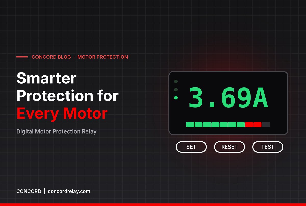
Digital Motor Protection Relay: How It Works and Why
A digital motor protection relay watches the current a motor draws, compares it with the limits you set, and switches the motor off when something goes wrong. What sets it apart from older thermal and analog relays is that it measures, calculates and displays: you can see the running current, the cause of the last trip and how hard the motor is working, all from the front of the panel.
This guide explains how a digital motor protection relay works inside, how it differs from analog electronic and bimetal thermal relays, and where the upgrade pays for itself. Examples are drawn from the CONCORD EOCR SSD and EOCR 3DE / 3EZ, which are designed and built in India for Indian supply and site conditions.
What Is a Digital Motor Protection Relay?
It is an electronic relay, wired into the motor starter alongside the contactor, that protects an induction motor against running faults such as overcurrent, phase loss, locked rotor and, depending on the model, phase unbalance, reverse phase, rotor jam, undercurrent and ground fault. A 7-segment LED display shows measured current and trip causes, and settings are entered as numeric values.
It does not replace the short-circuit device. An MCCB or fuse upstream still clears short circuits; the digital relay handles the slower, more frequent faults that overheat and destroy windings.
How It Works: From CT to Trip Contact
1. Current sensing through CTs
Each motor line passes through a current transformer. The EOCR SSD uses two integral CTs; the EOCR 3DE / 3EZ measures all three phases. For motors beyond the direct range, external CTs with 5A secondary extend protection up to 600A running current. For very small motors, the line wire can be looped through the internal CT more than once so the relay reads small currents more precisely.
2. Signal processing in the MCU
The CT outputs are converted into signals the microcontroller can read. The MCU calculates the current in each phase, compares phases with each other to detect loss, unbalance or reversal, and runs timers for the start delay and operating time. Because the measurement is electronic, it is not affected by ambient temperature in the way a bimetal strip is.
3. Decision and timing
Settings define what counts as a fault and how long to wait:
- Current setting — the motor’s normal running current.
- D-Time / start delay — time allowed for the high inrush current during start, so the relay does not trip on a normal start. On the 3DE / 3EZ this is adjustable from 0 to 200 s.
- O-Time / operating time — how long an overcurrent may persist before tripping.
- Characteristic — definite time or, on the 3DE / 3EZ, thermal inverse with class 1-30.
4. Output and indication
When a fault is confirmed, the output contact changes state and drops the contactor. The display records the reason, such as “oc”, “PL-2” or “-LC-” on the SSD. After a trip, the relay must be reset (manually, electrically from a remote point or, on the 3DE / 3EZ, automatically after a set time) before the motor can restart.

Digital vs Analog vs Thermal Relays
| Aspect | Bimetal thermal relay | Analog electronic relay (e.g. EOCR SS) | Digital relay (EOCR SSD, 3DE / 3EZ) |
|---|---|---|---|
| Sensing | Heating of a bimetal strip | Integral CTs, solid-state circuit | Integral or external CTs, processed digitally |
| Ambient sensitivity | Affected by panel temperature | Ambient insensitive | Ambient insensitive |
| Phase loss detection | Indirect, via extra heating | Yes | Yes, with faulty phase identified (SSD) |
| Current reading | None | LED status | Numeric ammeter display |
| Trip cause | Not shown | LED indication | Coded on display |
| Extra functions | None | Locked rotor | Locked rotor; on 3DE / 3EZ also unbalance, reverse phase, jam, undercurrent, ground fault (3EZ) |
Analog electronic relays remain a sound choice for simple, cost-sensitive panels. The digital relay earns its place where visibility and wider protection matter. Our article on types of electronic motor protection relay covers the classification in more detail.
CONCORD Digital Models: SSD and 3DE / 3EZ
EOCR SSD
The EOCR SSD is a 2 CT based relay with a digital display and a direct replacement for the EOCR SS. It shows the maximum current in any phase and suits single-phase or three-phase motors. Ranges are 0.5-6A, 3-30A and 10-60A, with D-Time 1-30 s and O-Time 1-10 s. Phase loss trips within 3 s, and locked rotor operates immediately if 200% or more of set current continues after D-Time.
EOCR 3DE / 3EZ
The EOCR 3DE / 3EZ is an MCU-based digital relay for three-phase motors. It adds phase unbalance, reverse phase, rotor jam and undercurrent (useful for pump dry-run detection), a load factor bar graph from 65% to 100%, and automatic reset from 0.5 s to 20 minutes. The 3EZ adds ground fault protection with a CBCT / ZCT. One model covers 0.5A to 600A with external CTs, which cuts the number of relay variants a plant needs to stock.
A full breakdown of each display and setting is in our guide to digital overload relay features.
Where a Digital Relay Pays Off
- Remote or unattended pump stations: undercurrent catches dry running, and the trip cause tells the visiting technician what happened.
- Plants with many motors: one wide-range model with external CTs simplifies spares.
- Critical process motors: phase unbalance and ground fault detection give warning of supply and insulation problems before a burnout.
- High-inertia loads: the long start delay on the 3DE / 3EZ avoids nuisance trips on fans and crushers.
- Sites with frequent nuisance trips: the ammeter display lets you set the relay against actual running current rather than guessing from the nameplate.
- Hot panel rooms: electronic sensing does not drift with ambient temperature.
A single avoided rewind or unplanned shutdown can outweigh the price difference between a thermal relay and a digital motor protection relay, particularly on submersible pumps where pulling the motor is itself expensive.
Frequently Asked Questions
How does a digital motor protection relay measure current?
Through current transformers, either built into the relay or mounted externally with a 5A secondary. A microcontroller processes the CT signals to calculate phase currents and detect faults.
Is a digital relay better than a thermal overload relay?
For most applications, yes. It is ambient insensitive, detects phase loss directly, displays motor current and shows the trip cause. A thermal relay only reacts to heating and gives no diagnostic information.
Can a digital relay be used on single-phase motors?
The EOCR SSD is suitable for single-phase or three-phase motors. The EOCR 3DE / 3EZ is designed for three-phase motors.
What is the difference between EOCR 3DE and 3EZ?
Both share the same digital platform. The 3EZ adds ground fault (earth leakage) protection using a CBCT / ZCT to measure leakage current.
Does a digital relay need a separate power supply?
It needs a control supply. The 3DE / 3EZ accepts 100-240VAC/DC free voltage or 24VAC/DC; the SSD accepts a universal 24-240V AC/DC supply.
Planning an upgrade from thermal relays or specifying a new MCC? Talk to CONCORD for help choosing the right model and settings. Call or WhatsApp +91 96670 40511, email contact@concordrelay.com, or visit our contact page. The CONCORD EOCR brochure has complete specifications for the range.