
Current Sensing Protection Relay: How It Protects Motors
Every fault that harms an induction motor eventually shows up in the current it draws. A jammed conveyor, a lost phase, a pump running without water or a bearing that is starting to seize all change the size or balance of the line current. A current sensing protection relay reads that signal continuously and opens the starter coil before heat, rather than the fault itself, ruins the winding.
This article explains how current sensing works inside an electronic motor protection relay: integral and external current transformers, looping for small motors, the 5A secondary arrangement for large motors, and what each change in current tells you about motor health. It is written for maintenance engineers, panel builders and OEMs who want to understand the principle before choosing or setting a relay.
What Is a Current Sensing Protection Relay?
A current sensing protection relay measures the current in the motor supply lines and compares it with the values you set. When the measured current crosses a limit for longer than the set time, its output contact changes state and drops out the contactor. Unlike a bimetal thermal overload relay, which relies on a strip bending as it heats, an electronic relay converts current into a measured value and makes decisions on that value. This is why electronic relays are ambient insensitive: a hot panel in May does not shift the trip point the way it does with a bimetal element.
CONCORD’s EOCR motor protection relays all work on this principle. They use solid state or microcontroller (MCU) circuits, have built-in current transformers, and draw very little energy from the control supply.
How Current Sensing Works: Integral CTs, Looping and External CTs
Integral current transformers
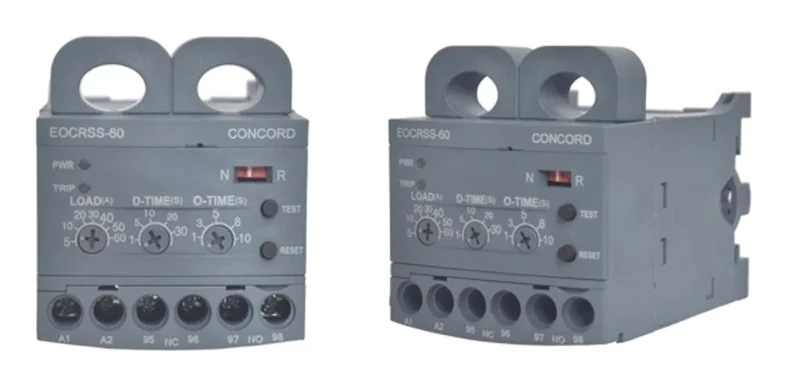
The motor line wires pass through windows in the relay body. Each window is the primary of a small current transformer, and the secondary feeds the measuring circuit. Depending on the model, the relay has two or three integral CTs. The EOCR SSD is a 2 CT based digital relay, while the EOCR DS and EOCR 3DE/3EZ use three integral CTs, so every phase is measured directly.
Looping for small motors
A CT is most accurate in the upper part of its range. For a small motor, the line wire can be passed through the CT window more than once. Each extra turn multiplies the current the relay sees, so the effective setting range drops and measurement becomes more precise. The looping table for the 05 type (0.5-6A) relay is:
| Number of turns | 05 type range (A) | 30 type range (A) | 60 type range (A) |
|---|---|---|---|
| 1 | 0.5-6 | 2.5-30 | 5-60 |
| 2 | 0.25-3 | 1.25-15 | 2.5-30 |
| 3 | 0.17-2 | 0.83-10 | 1.7-20 |
| 4 | 0.13-1.5 | 0.62-7.5 | 1.25-15 |
| 5 | 0.1-1.2 | 0.5-6 | 1-12 |
Use the same number of turns on every phase, and select the setting range from the table that matches the number of turns used.
External CTs with 5A secondary for large motors
For motors above the direct range, external CTs with a 5A secondary step the line current down. An 05 type relay (0.5-6A) wired to these CTs can protect motors with running currents up to 600A. CONCORD supplies SCR-CT single hole CTs (SCR-CT 100, 200 and 600) and 2-hole or 3-hole combined CTs (100:5 to 400:5, class 1.0, 5VA) for base mounting inside the panel. On digital models, the displayed current can be selected to match the CT ratio, so the operator reads actual motor amps.
What Motor Current Tells You About Motor Health
Once current is measured accurately, a relay can recognise several distinct conditions. Each has its own signature:
- Overcurrent (overload): current stays above the set value. Typical causes are mechanical overload, worn bearings, low supply voltage or a clogged impeller.
- Phase loss (single phasing): one line current falls to near zero while the other two rise. A blown fuse or loose termination is the usual cause.
- Phase unbalance: line currents differ significantly from each other, usually because of unequal supply voltages or a developing winding fault.
- Locked rotor or jam: current stays very high, often several times the full load value, after the starting period should have ended.
- Undercurrent: current drops below normal. On pumps this usually means dry running or loss of suction; on fans or conveyors it can mean a broken belt or coupling.
- Reverse phase: the phase sequence of the currents is wrong, so the motor would run backwards.
- Ground fault: the vector sum of the line currents is not zero because some current is leaking to earth. This needs a zero-sequence CT (ZCT/CBCT).
| Condition | EOCR SS | EOCR SSD | EOCR DS | EOCR 3DE/3EZ |
|---|---|---|---|---|
| Overcurrent | Yes | Yes | Yes | Yes |
| Phase loss | Yes | Yes | Yes | Yes |
| Locked rotor | Yes | Yes | Yes | Yes |
| Reverse phase | – | – | Yes | Yes |
| Phase unbalance, rotor jam | – | – | – | Yes |
| Undercurrent (dry run) | – | – | – | Yes |
| Ground fault | – | – | – | 3EZ with ZCT |
Timing: D-Time and O-Time
Current alone is not enough; the relay also needs to know when to ignore it. A motor draws a high inrush current while starting. The D-Time (starting delay time) is the period allowed for the motor to settle to its normal running current, which prevents nuisance trips during start. The O-Time (operating time) is how long an overcurrent may continue after start before the relay trips. On the EOCR SS and DS, D-Time is adjustable from 0.2-30 s and O-Time from 0.2-10 s. On the 3DE/3EZ, the start delay can be set from 0-200 s, which suits high-inertia loads such as large fans.
A practical approach is to set D-Time a little longer than the measured starting time, and O-Time short enough that the winding is not overheated but long enough to ride through brief load peaks. Our post on overload protection relay specifications explains each of these settings in more detail.
Current Sensing Protection Relay vs Thermal Overload Relay
Bimetal thermal relays are inexpensive, but they have limits that current sensing relays address:
- Accuracy: electronic measurement holds its setting across ambient temperatures; bimetals drift with panel heat.
- Range: one electronic relay covers a wide adjustment range, and with looping or external CTs, from fractional amps up to 600A.
- Phase loss: electronic relays detect single phasing directly from the current pattern rather than waiting for heat to build.
- Diagnosis: LED or 7-segment trip indication tells the technician why the motor stopped.
- Testing: a front-panel TEST button checks relay health without energising the motor circuit.
Neither type is a short-circuit device. Short-circuit protection is the job of the MCCB, MPCB or fuses upstream, and the relay should always be coordinated with them.
Frequently Asked Questions
What does a current sensing relay do in a motor starter?
It measures motor line current through CTs and opens the contactor coil circuit when the current shows an overload, phase loss, locked rotor or other fault for longer than the set time.
Can a current sensing relay protect a motor above 60A?
Yes. Using external CTs with a 5A secondary, an 05 type EOCR relay can protect motors with running currents up to 600A.
Why loop the wire through the relay CT?
Looping multiplies the current seen by the relay, giving a lower, more precise setting range for small motors. For example, an 05 type relay with 3 turns covers 0.17-2A.
Does a current sensing relay detect dry running?
Only if it has an undercurrent function. The EOCR 3DE/3EZ has an adjustable low-current setting that trips when a pump’s current falls because it has lost water.
Is a current sensing relay affected by panel temperature?
No, not in the way a bimetal relay is. Electronic sensing keeps the trip point stable regardless of ambient temperature inside the panel.
Need help picking the right relay, CT ratio or looping arrangement for your motors? Talk to CONCORD’s application team on +91 96670 40511 (call/WhatsApp) or email contact@concordrelay.com. You can also send an enquiry or download the CONCORD EOCR brochure for full specifications.