
Overload Protection Relay Specifications: How to Read Them
Two relays can look identical in a catalogue photo and behave very differently in a panel. The difference sits in the spec sheet: current range, timing adjustments, trip characteristic, control voltage, contact configuration and mounting. Reading overload protection relay specifications correctly is what separates a relay that protects the motor from one that trips on every start or never trips at all.
This guide explains each line of a typical spec sheet, what it means in practice, and what to check against your motor and panel. A consolidated specification table for the CONCORD EOCR range follows, taken from the CONCORD EOCR brochure 2025-26.
Current Setting Range
The current range is the band of motor running currents the relay can be set to. CONCORD EOCR relays come in three base ranges, typically labelled 05, 30 and 60 types (0.5-6A, 3-30A and 5-60A or 10-60A depending on model). Choose the range so the motor’s full-load current sits comfortably inside it, not at the extreme ends.
Looping for small motors
For small currents, the line wire can be passed through the internal CT more than once. Each extra turn divides the effective range. For the 05 type, one turn covers 0.5-6A, two turns 0.25-3A, three turns 0.17-2A, four turns 0.13-1.5A and five turns 0.1-1.2A. The 30 and 60 types scale in the same way.
External CTs for large motors
Above the direct range, external CTs with 5A secondary are used with an 05 type relay, extending protection to motors with running currents up to 600A. CONCORD offers 2-hole and 3-hole combined CTs (100:5 to 400:5, class 1.0, 5VA) and single hole SCR-CT 100, 200 and 600.
Timing Settings: D-Time and O-Time
D-Time (starting delay) is the time allowed for the motor to reach normal running current after switching on. During this period the high inrush current does not cause a trip. Set it slightly longer than the actual starting time.
O-Time (operating time) is how long the relay waits once running current exceeds the set value before it trips. Short O-Time protects the winding sooner; too short may trip on brief, harmless load peaks.
Spec sheets give the adjustable range for each, for example D-Time 0.2-30 s and O-Time 0.2-10 s on the EOCR SS and DS. The EOCR 3DE / 3EZ uses a manoeuvre (start) delay of 0-200 s for long-starting loads.
Trip Characteristic: Definite vs Inverse
A definite time characteristic trips after the set O-Time regardless of how far current exceeds the setting. It is simple to set and predictable. A thermal inverse characteristic trips faster on heavy overloads and slower on light ones, modelling motor heating. Inverse relays are specified by class; the EOCR 3DE / 3EZ offers class 1-30. The EOCR DS is definite time as standard, with inverse available on request.
Control Voltage, Contacts and Other Specifications
Control (auxiliary) supply
The relay needs its own supply. Check it matches your control circuit: the EOCR SS and SSD accept a universal 24-240V AC/DC supply, the DS uses 180-260VAC, and the 3DE / 3EZ takes 100-240VAC/DC free voltage or 24VAC/DC.
Output contacts
Contact configuration tells you how the relay interfaces with the contactor and alarm circuit. SPST means a single make or break contact; SPDT (1C) is a changeover. Ratings such as 3A/250VAC define what the contact can switch directly; it drives the contactor coil, not the motor.
Fail-safe and NVR
In a fail-safe (normally energised) configuration, the output changes state if the relay loses its own supply, so the motor stops rather than running unprotected. The EOCR SS offers user-selectable fail-safe / non-fail-safe and an NVR (No Volt Release) function; the DS contact is normally energised.
Reset
Manual reset is by the front RESET button; electrical remote reset lets an operator reset from a control desk. The 3DE / 3EZ also offers automatic reset, adjustable from 0.5 s to 20 minutes.
Mounting
All CONCORD EOCR models mount on 35mm DIN rail or directly on a base plate.
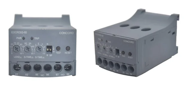
CONCORD EOCR Overload Protection Relay Specifications Table
| Specification | EOCR SS | EOCR SSD | EOCR DS | EOCR 3DE / 3EZ |
|---|---|---|---|---|
| Type | Analog, solid state | Analog with digital display, 2 CT | MCU based, 3 integral CTs | MCU based digital, 3-phase |
| Current range | 0.5-6A, 3-30A, 5-60A | 0.5-6A, 3-30A, 10-60A | 0.5-6A, 3-30A, 10-60A | 0.5-60A definite; 0.5-32A inverse |
| Above range | External CT (above 60A) | External CT | External CT (100A and above) | External CT, up to 600A |
| D-Time / start delay | 0.2-30 s | 1-30 s | 0.2-30 s | 0-200 s |
| O-Time | 0.2-10 s | 1-10 s | 0.2-10 s | 0.2-30 s (definite) |
| Characteristic | Definite | Definite | Definite (inverse on request) | Definite / thermal inverse, class 1-30 |
| Control supply | 24-240V AC/DC | 24-240V AC/DC | 180-260VAC | 100-240VAC/DC or 24VAC/DC |
| Contacts | 2 SPST 3A/250VAC | 2 SPST 3A/250VAC | 1 SPDT 3A/250VAC | 3A/250VAC: 1a1b, warning, undercurrent |
| Phase loss trip | Within O-Time | Within 3 s | Within 4 s | Yes, shown on display |
| Indication | 2 LEDs | 7-segment display | 2 LEDs, fault diagnosis | 7-segment display, bar graph |
| Mounting | 35mm DIN / base | 35mm DIN / base | 35mm DIN / base | 35mm DIN / base |
Product pages for the EOCR SS, EOCR DS and EOCR 3DE / 3EZ carry further detail.
Overload Protection Relay Specifications Checklist
- Motor full-load and actual running current, and whether looping or external CTs are needed
- Single-phase or three-phase motor
- Starting method and starting time, to set D-Time
- Faults to cover: phase loss, locked rotor, reverse phase, unbalance, undercurrent, ground fault
- Control voltage available in the panel
- Contact type needed for contactor and alarm wiring
- Fail-safe requirement and reset method
- Upstream MCCB or fuse for short-circuit protection, which the relay does not provide
For help weighing these points by application, see our guide to the best motor protection relay, or the digital overload relay features explainer.
Frequently Asked Questions
What is the difference between D-Time and O-Time?
D-Time is the starting delay that lets the motor pass its inrush current without tripping. O-Time is the delay before tripping once running current exceeds the set value.
How do I choose the current range of an overload relay?
Pick a range in which the motor’s running current sits comfortably, not at either extreme. Use looping for very small motors and external CTs above the direct range.
What does fail-safe mean on a protection relay?
The output contact is held energised in normal operation, so loss of relay supply causes a trip rather than leaving the motor running unprotected.
Can an overload relay be used with a 400A motor?
Yes, with external CTs of 5A secondary. CONCORD EOCR relays protect motors up to 600A running current this way.
Do overload protection relay specifications include short-circuit protection?
No. Overload relays protect against overcurrent and running faults. Short circuits must be cleared by an upstream MCCB or fuse.
Need help reading a spec sheet against your motor list? Talk to CONCORD for selection support. Call or WhatsApp +91 96670 40511, email contact@concordrelay.com, or use the contact page. The complete CONCORD EOCR brochure is available for download.